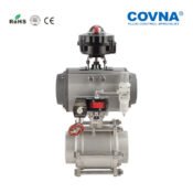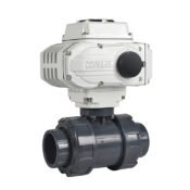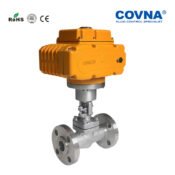


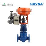
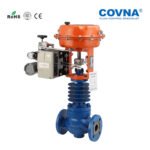

Pneumatyczny wysokotemperaturowy zawór regulacyjny WCB z górną tuleją prowadzącą serii ZJHM
ZJHM Series Top Guide Sleeve WCB Pneumatic High Temperature Control Valve, which is a low flow resistance control valve, multi spring actuator of low height, light weight, simple equipment. High temperature pneumatic control valve flow channel was streamlined S, the control valve has the advantages of compact structure, light weight, flexible action, small pressure drop loss, valve capacity, flow characteristics of precision, convenient maintenance, High temperature pneumatic control valve regulating mechanism adopts balanced valve plug valve structure, has good stability, not easy to vibration, low noise the temperature sensitivity, small. High temperature pneumatic control valve is especially suitable for leakage requirements is not high, high temperature.
Port size:DN15-DN300
Pressure:PN10-PN64 CL150-CL600
Medium:Water,steam,oil,etc.
Temperature :100~450℃
Body material:WCB,WC6,WC9,CF8,CF8M,etc.
Advantages of ZJHM Series Top Guide Sleeve WCB Pneumatic High Temperature Control Valve:
● It is cost-effective and safe to be used,which can help you save cost of the whole system and maintenance.
● It has a simple structure and a big torque, explosion-proof with short actuating times,optimized actuating forces and reliable tight sealing.
● It can perfectly avoid problems of friction, corrosion, and emissions.
● It is of low center of gravity, high vibration resistance and easy to install.
● Simple to control, rapid response, and intrinsic safety, no need to take additional explosion-proof measures.
● Fluid channels in a s- shaped streamline, small pressure drop loss large flow, wide adjustment range, high precision flow.
● Especially suitable for leakage requirements is not high, high temperature
Working Principle Of high temperature Pneumatic control valve
By receiving the control signal pressure output by the standard electric signals of the regulator(via electricity-air positioner or electricity-air converter),the valve
opening is changed, so as to change the flow of the medium to be regulated and then allow parameters such as flow, pressure,temperature and liquid level to be regulated. As a result, the production process automation is achieved.
After the extraneous pneumatic pressure signal is input into the diaphragm chamber, it will act on the diaphragm to produce a thrust. The thrust then compress the spring pack, and move the push rod, which drives the spindle to open (close) of the valve clack, until the balance is achieved between the thrust and reaction ofthe compressed spring pack and the clack is in a stable position of the stroke.It’s concluded from above principle, There’s a definite proportional relation between the clack and the input pressure signal.
Technical Parameters of Valve Actuator :
| Nominal Size DN (mm) | 20 | 25 | 32 | 40 | 50 | 65 | 80 | 100 | 125 | 150 | 200 | 250 | 300 | ||||
| 10 | 12 | 15 | 20 | ||||||||||||||
| Rated Flow Coefficient CV | High accuracy flow characteristic clack | 1.6 | 2.5 | 4.0 | 6.3 | 10 | 17 | 24 | 44 | 68 | 99 | 175 | 275 | 360 | 630 | 900 | 1440 |
| High capacity flow characteristic clack | 1.8 | 2.8 | 4.4 | 6.9 | 11 | 21 | 30 | 50 | 85 | 125 | 200 | 310 | 440 | 690 | 1000 | 1600 | |
| Rated Stroke(mm) | 10 | 16 | 25 | 40 | 60 | 100 | |||||||||||
| Effective Diaphragm Area cm2 | 280 | 400 | 630 | 1000 | 1600 | ||||||||||||
| Inherent Regulation Ratio | 50:1 | ||||||||||||||||
| Nominal Pressure MPa | 1.6 / 4.0 / 6.4 | ||||||||||||||||
| Sevice Temperature | -100~-60℃; -200~-100℃; -250~-200℃ | ||||||||||||||||
| Ambient Temperature | -30~70℃ | ||||||||||||||||
| Air Supply Pressure KPa | 0.14 / 0.25 / 0.40 | ||||||||||||||||
| Spring Range KPa | 20~100(Basic type) / 40~200 / 80~240 | ||||||||||||||||
| Connection Thread | G1/4″ , M16X1.5 | ||||||||||||||||
Performance of High Temperature Pneumatic Control Valve:
| High temperature pneumatic control valve Flow characteristic |
Linear, percentage, quick open | |
| Allowable range | 50: 1 (CV<6.3 30: 1) | |
| Rated Cv value | Percentage CV1.6~630 ,linear CV1.8~690 | |
| Pneumatic control valve Allowable leakage | Metal seal: IV grade(0.01% rated capacity) Leakage standard: GB/T 4213 |
|
| High temperature pneumatic control valve Performance | ||
| Intrinsic error % | ±1.5 | |
| Return difference, % | ≤1.5 | |
| Dead zone, % | ≤0.6 | |
| Difference from beginning to end point, % | ±2.5 | |
| Rated travel difference, % | ≤2.5 | |
Dimension of ZJH Series Pneumatic Diaphragm Control Globe Valve:

Weight table of Pneumatic diaphragm regulating valve

Profil firmy:
Profil fabryczny:
Certyfikaty firmy:
Opakowanie i wysyłka:
Jako profesjonalny producent elektrycznych zaworów kulowych, COVNA dąży do zapewnienia naszym klientom najwyższej jakości produktów w najbardziej konkurencyjnych cenach, terminowych dostaw i pełnego serwisu gwarancyjnego z kompleksową obsługą od początku do końca, obejmującą konsultacje po obsługę posprzedażową, pełne wsparcie pod każdym względem i zapewnienie, że towarzyszą Ci na każdym etapie projektu.
●22 years manufacturer of actuated valves
●Mass customaztion acceptable. 3 production base, large stock,
●Short lead time, same day shipping.
●German imported manufacturing facilities, 100% Q.C passed before shipping, quality assured.
●Industrial standard 1 year (12 months) warranty.
●ISO 9001 certificated, with extra certifications include CE, TUV, RoHS, SGS, BV, explosion & fire safe.
●OEM / ODM service available. Can do JIS 5K / 10K, ANSI 150lb / 300lb / 600lb / 900lb standard.
●More infomation, pls send message to us. Quote will be provided within 2 hours!
Parametry techniczne siłowników:
| Nominal Diameter | G 3/4″ | 20 | 25 | 40 | 50 | 65 | 80 | 100 | 150 | 200 | 250 | 300 | |||||||||||||||||||
| Valve Seat Diameter | 3 4 5 6 7 8 | 10 | 12 | 15 | 20 | 20 | 25 | 25 | 32 | 40 | 32 | 40 | 50 | 40 | 50 | 65 | 50 | 65 | 80 | 65 | 80 | 100 | 100 | 125 | 150 | 125 | 150 | 200 | |||
| Rated Flow Coefficient Cv | High Accuracy Flow Characteristic Clack | 0.08 0.12 0.20 0.32 0.50 0.80 | 1.8 | 2.8 | 4.4 | 6.9 | 6.9 | 11 | 11 | 17.6 | 27.5 | 17.6 | 27.5 | 44 | 27.5 | 44 | 69 | 44 | 69 | 110 | 69 | 110 | 176 | 176 | 275 | 440 | 275 | 440 | 690 | 1000 | 1600 |
| High Capacity Flow Characteristic Clack | 1.6 | 2.5 | 4 | 6.3 | 6.3 | 10 | 10 | 16 | 25 | 16 | 25 | 40 | 25 | 40 | 63 | 40 | 63 | 100 | 63 | 100 | 160 | 160 | 250 | 400 | 250 | 400 | 630 | 900 | 1440 | ||
| Rated Strock(mm) | 10 | 16 | 25 | 40 | 60 | 100 | |||||||||||||||||||||||||
| Effective Diaphragm Area (cm2) | 220 | 350 | 560 | 900 | 1400 | ||||||||||||||||||||||||||
| Inherent Regualtion Ratio | 50:1 | ||||||||||||||||||||||||||||||
| Nominal Pressure MPa | 0.16 1.6 4.0 6.4 (ANSI125 150 300 600LB)(JIS10 16 20 30 40K) | ||||||||||||||||||||||||||||||
| Sevice Temperature | -20 to 200℃ -40 to 250℃ -40 to 450℃ -60 to 450℃ | ||||||||||||||||||||||||||||||
| Ambient Temperature | -40 to 85℃ | ||||||||||||||||||||||||||||||
| Air Supply Pressure KPa | 0.14(0.25 0.4) | ||||||||||||||||||||||||||||||
| Spring Range KPa | 20 to 100(40 t o200 80 to 40 20 to 60 60 to 100) | ||||||||||||||||||||||||||||||
| Connection Threaded | Female Thread M10×1 | ||||||||||||||||||||||||||||||


_2022_03(1).png)


(1).png)
